Technology
Fuel-Tolerant Containerized Gasification CHP
Analema works with fuel-tolerant containerized gasification CHP designed for mixed low-grade forestry material, local heat, and compact deployment.
Inside the unit
The unit, inside and out.
The manufacturer’s own cutaway of the HKW300 machine train inside its container — six modules in the order fuel moves through them.
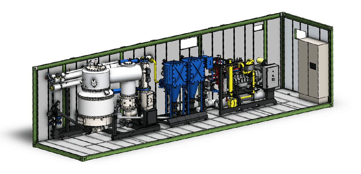
- 01Drying & screened feedCFD drying bunker, bucket elevator and integrated screen.
- 02Multi-stage gasifierInsulated vessel converts screened fuel to producer gas.
- 03Syngas cooling & heat recoveryGradual gas cooling; usable heat returned to nearby loads.
- 04Gas cleaning (baghouse)Dry plate filters dedust the gas; ash out by screw.
- 05Gas engine CHPGas engine coupled to an alternator for power.
- 06PLC controlsFully automatic PLC control for low-staff operation.
Built for real forestry material
Forestry does not produce a uniform fuel. Moisture, species, and piece size vary by season and by site. Analema's selected technology is a fuel-tolerant containerized gasification CHP system, chosen specifically because it accepts mixed, inconsistent low-grade forestry material rather than requiring forestry to be reshaped around the plant.
How the system works
Feedstock moves through the unit in process order: intake and fuel handling, gasification, gas cleanup, an engine-generator set, heat recovery, and a monitoring and control layer. Each stage is sized to match the scale of a local, forestry-fed supply chain rather than a utility-scale plant.
Typical unit specifications
The figures below describe a typical unit and are labeled accordingly — actual performance depends on site, fuel, and operating conditions.
A compact, deployable footprint
The containerized format keeps the core unit to roughly 30 m², with additional space for fuel drying and stockyard handling on site. That compactness supports faster siting and deployment on land near the forestry supply it draws from, rather than requiring utility-scale infrastructure.
Heat and power that support forestry
Electrical output can serve local use or grid connection. Thermal output can support wood drying, sawmill operations, agriculture, and other local industry — uses that strengthen the forestry value chain the fuel came from, rather than treating the plant as an isolated asset.
Monitoring and operations
The unit is designed for low on-site staffing with remote monitoring, so a facility sized for a local supply chain does not require utility-scale operations overhead.
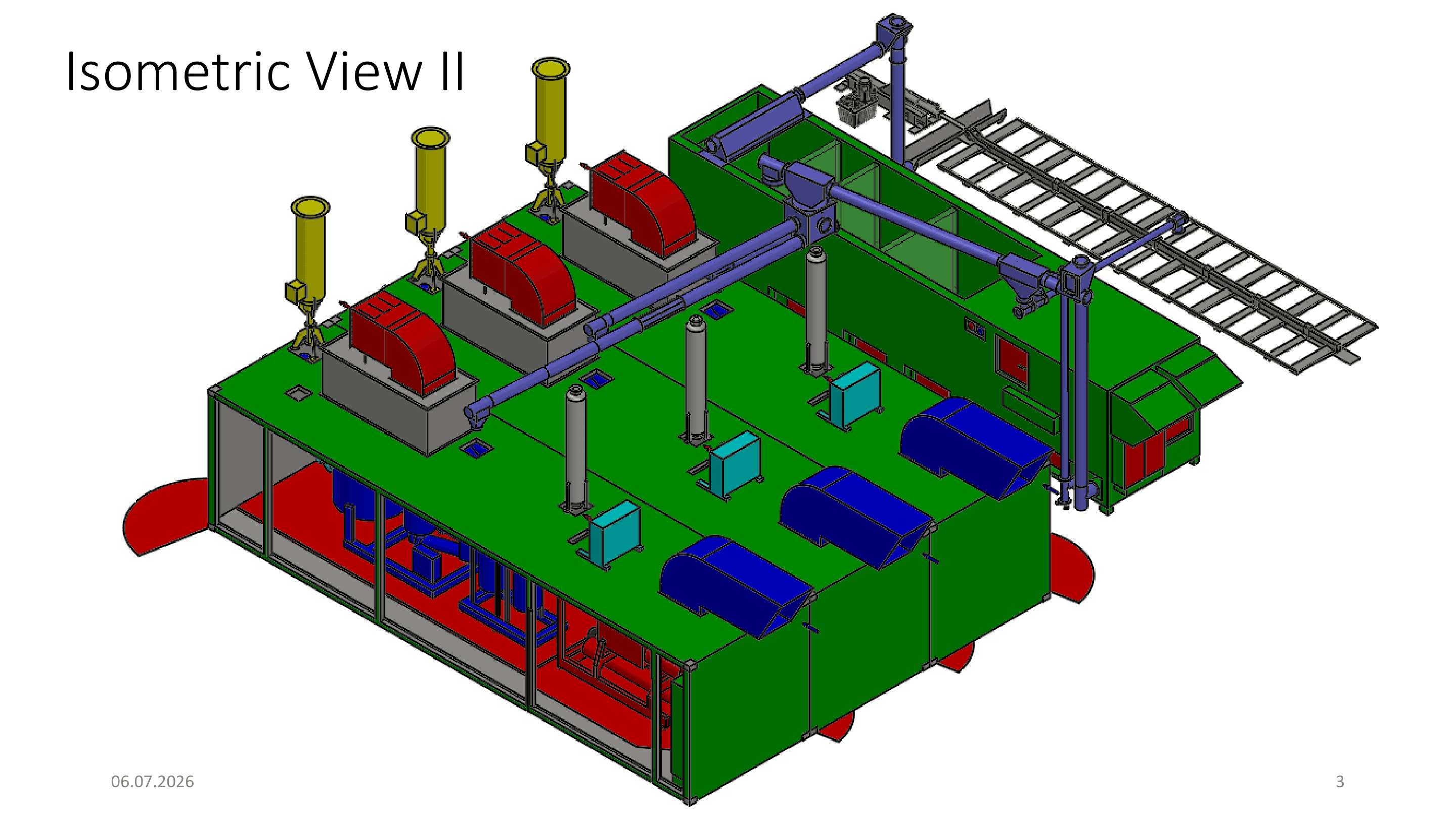
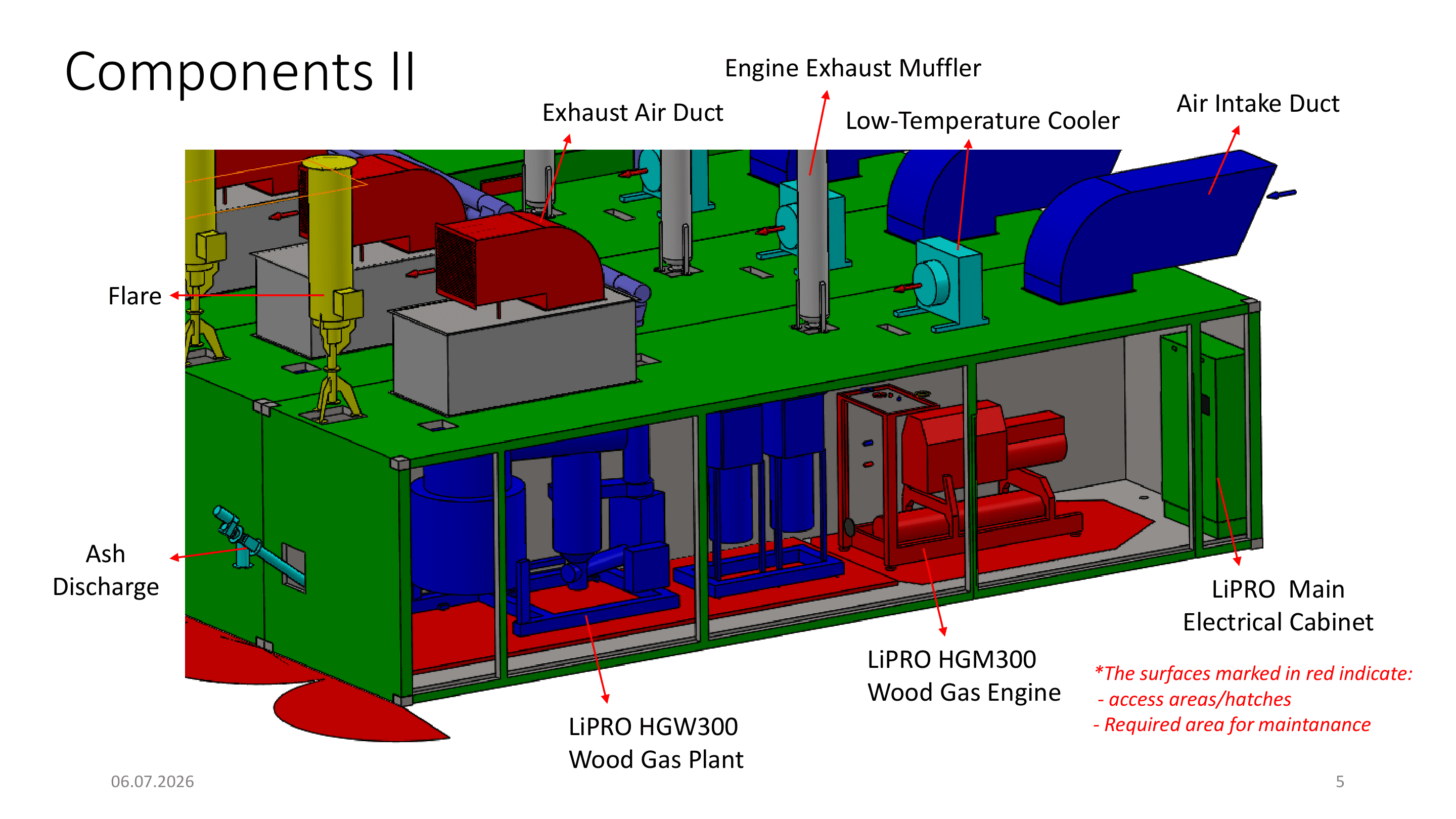
- Intake hopper — mixed low-grade wood, about 1.64 t/day (bone-dry) for a typical unit; roughly 3.29 t/day as delivered at ~50% green moisture.
- Auger — the screw conveyor feeds fuel into the reactor.
- Gasifier — fuel is converted to syngas.
- Cyclone and filter — the syngas is cleaned.
- Engine-generator — cleaned syngas drives ~100 kWe of electrical output.
- Heat recovery — captures ~232 kW of thermal output for kilns and greenhouses.
- Controls — the unit monitors and regulates the process.
An authorized LiPRO partner in Japan
Analema GK is an authorized partner of LiPRO Energy for Japan. We are not describing someone else's equipment — we develop, sell, and support LiPRO wood-gasification CHP for this market, from the fuel chain through long-term operation.
The manufacturer's track record
The technology is not a prototype. The facts below are sourced and attributed to the manufacturer, LiPRO Energy.
LiPRO Energy GmbH & Co. KG, based in Wardenburg, Germany and founded in 2015, manufactures multi-stage wood-gasification combined-heat-and-power plants and marked its tenth year in 2025.
Source: lipro-energy.de; Forst & Technik, issue 10-2023.German trade press reported that LiPRO's reference map showed about eleven installed plants, concentrated around Lake Constance (Baden-Württemberg) and in Vorarlberg, Austria.
Source: Forst & Technik, issue 10-2023.In February 2024, measurements by Swiss institutes found LiPRO's wood gas to be largely tar-free and at the upper end of current technical possibilities for CO, NOx and particulate matter.
Source: LiPRO HKW50 datasheet (result reported by LiPRO).The process spatially separates pyrolysis, oxidation — around 1,000 °C, where tar precursors are thermochemically cracked — and reduction, then cleans the gas with a dry fabric filter, so no wet scrubbing of the synthesis gas is required.
Source: LiPRO HKW300 datasheet; LiPRO technology page.
Honest fuel specification
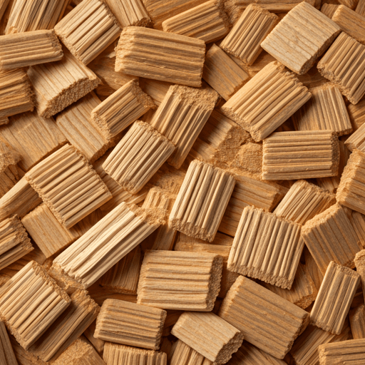
The plant runs on P45-class wood chips at under 10% moisture — a genuinely demanding fuel window. That window is met by the fuel chain, not wished away: a CFD moving-floor dryer brings wet chips down to specification, and screening holds piece size and fines within range. In practice this drying-and-screening chain is the fuel-flexibility mechanism — it is what lets mixed, low-grade forestry material become a fuel the gasifier accepts consistently.
Heat grade that fits a kiln schedule
The high-temperature configuration delivers roughly 100 °C hot water. That comfortably covers the 60–90 °C schedules typical of sugi and hinoki kiln drying, which is what makes the heat genuinely useful to a sawmill rather than a by-product to shed.
Grid interconnection
At this scale, interconnection is typically at the 6.6 kV distribution class. Output can be sold under a FIT or FIP arrangement, or used on-site for self-consumption, depending on the project. Because interconnection timelines and available feeder capacity vary by location, Analema engages the local utility early — grid reality is assessed before a site is committed, not after.
Emissions and residuals
The gas is cleaned by dry fabric filtration rather than a wet scrubber, so there is no scrubber wastewater to treat or dispose of. The solid streams are ash and char from the reactor and grate. Air-quality, waste, and fire-safety permits apply and are engaged as part of siting; specific requirements depend on location and configuration.
Common questions
What is wood-gasification CHP?
It converts wood chips into a combustible synthesis gas, then burns that gas in an engine-generator set to produce both electricity and usable heat. Analema works with a fuel-tolerant, containerized small-scale biomass CHP system chosen to accept mixed, low-grade forestry material.
What fuel does it need?
P45-class wood chips at under 10% moisture. A CFD moving-floor dryer and screening bring mixed, low-grade forestry material to that specification — the drying-and-screening chain is what makes the fuel flexible.
Can the heat actually be used?
Yes. The high-temperature configuration delivers around 100 °C hot water, which fits the 60–90 °C schedules of sugi and hinoki kiln drying and other local industry.
How is the gas cleaned?
The process cracks tar precursors thermochemically in a high-temperature oxidation stage, then cleans the gas with a dry fabric filter, so no wet scrubbing of the synthesis gas is required.
Engineering layout