Reference Design
Reference Design
Analema's reference configuration: a three-unit LiPRO HKW300 wood-gasification CHP cascade, fueled by local forestry thinnings and sawmill residues.
Reference configuration — 3× HKW300 cascade
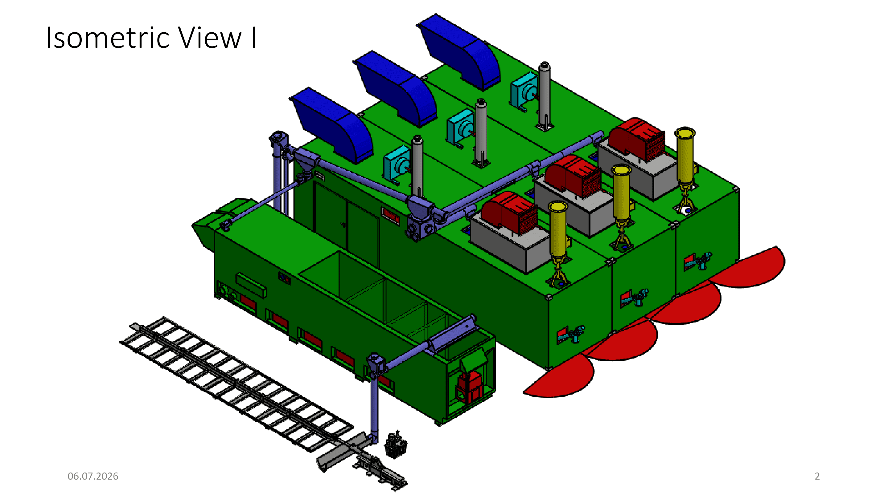
Analema's reference configuration is three LiPRO HKW300 wood-gasification CHP units run in cascade, paired with CFD belt drying, in a containerized Mobile Cube format. The figures on this page are design figures for this configuration — not measurements from an operating plant.
The configuration
Three HKW300 units run in cascade so fuel handling, drying, and heat recovery scale together rather than as three separate, unconnected units. Each unit is a typical 100 kWe / 232 kWth containerized gasification CHP; run together, the cascade is designed for the outputs below. All cascade figures are design figures, scaled from the typical single-unit specifications — actual performance depends on site, fuel, and operating conditions.
The fuel chain
The configuration is designed to run on mixed low-grade local forestry material — thinnings with no higher-value market — plus sawmill residues such as bark, offcuts, and sawdust. Biomass is the last stream in the cascade, not the first: it uses what construction timber, panels, and paper markets cannot.
What it proves
Because a three-unit cascade is designed to run on contracted local thinnings and mill residues, the same configuration is repeatable at any forestry-fed site — a local model, not a one-off plant.
Where the model applies
The same fuel-chain and grid criteria can be applied to forestry-fed sites across Kyushu and beyond. Analema assesses candidate locations against those criteria; specific sites are named here only once there is something concrete to disclose.
Who this works for
Forestry suppliers, including 森林組合
A steady, contracted buyer for low-grade material that otherwise has no market. Long-term offtake gives thinning operations a more predictable revenue stream.
Sawmills
Bark, sawdust, and offcuts become a revenue stream instead of a disposal cost. Nearby process heat can also support drying and other mill operations.
Municipalities
Forest maintenance is funded in part by energy revenue, not public budgets alone. A local plant also supports jobs and regional resilience.
Heat users
Nearby industry and facilities gain access to predictable, locally generated heat. That heat comes from a supply chain already rooted in the area, not a remote grid connection.
Investors & partners
Each project is small-unit and repeatable, with its fuel supply secured before construction. That combination reduces both fuel risk and permitting complexity compared with utility-scale biomass.
For investors: the economic frame
Illustrative only. The policy frame and development sequence below describe a reference-design project — not an offer, a forecast, or the terms of any specific project.
The policy frame
Japan's current FIT schedule includes a dedicated tariff band of ¥40/kWh for 未利用材 (unused local forestry material) biomass power under 2,000 kW — the band a forestry-fed small-scale project is designed to qualify under. That band exists to reward exactly the local-material model Analema builds. Actual eligibility, tariff, and term are set by the programme in force when a project is certified; nothing here is a revenue promise.
Three ways a block earns
The unit behind every figure
One block, on your land
Three LiPRO HKW300 units run in cascade, one CFD dryer, and one moving-floor fuel bay.
Reference configuration — design figures from the manufacturer specification and our published model, not measurements from an operating plant. No project is sited or in progress. This three-unit reference block is a distinct configuration from the ten-unit data-center block.
The same block above can be pointed at any one of three revenue modes. Every figure below is illustrative, on the assumptions stated — derived from our published larger reference model. A block-level statement of the underlying figures is available on request.
FIT
未利用材 under 2,000 kW at ¥40/kWh — confirmed for FY2026 certification (METI press release 2026-03-19; FY2027+ is under committee review). Government-fixed for 20 years. The figure below assumes ~2,074 MWh sold after a 10% 地域活用要件 local-use (self-consumption) share.
Illustrative ~¥83M/yr, fixed 20 years
Host PPA + contracted heat
A behind-the-meter power purchase to an on-site host, plus heat sold below oil parity — the model captures the full subsidy stack, and contracted heat is what makes the block's economics work.
Illustrative ~¥53M/yr power + contracted heat
Heat-led ESCO
We own and run the block; the host buys power below grid and heat below oil parity with no capex. Same physics, a different balance-sheet home.
Illustrative — priced per site, below the host's current oil and grid cost
Japan's named biomass failures were fuel-chain failures. Our model is fuel-first: our own fuel yard, a ≤30 km haul radius, and a blended feedstock designed to survive a cost shock. We never claim biomass beats the grid on ¥/kWh — the incentive architecture is what pays for self-consumption, and fuel discipline is what keeps the plant alive.
Because the blocks are identical, diligence is written once and deployed many times — one unit spec, one fuel-yard model, one permit path — for a portfolio exit to infrastructure capital.

An indicative development structure
A reference-design project moves through the same sequence regardless of site. Investor exposure and de-risking track this order.
Fuel chain
Secure long-term supply of local thinnings and mill residues, plus the drying-and-screening chain that brings them to specification.
Site
Identify and secure a site with a real, year-round heat sink near the forestry supply.
Permits & grid
Confirm interconnection at the distribution class and obtain the applicable air-quality, waste, and fire-safety permits.
Build
EPC and commissioning of the containerized cascade and its balance of plant.
Operate
Long-term operation, fuel logistics, and heat-and-power offtake over the life of the asset.